Connexion #
Pourquoi WebRTC a-t-il besoin d’un sous-système dédié pour la connexion ? #
La plupart des applications déployées aujourd’hui établissent des connexions client/serveur. Une connexion client/serveur nécessite que le serveur ait une adresse de transport stable et bien connue. Un client contacte un serveur, et le serveur répond.
WebRTC n’utilise pas un modèle client/serveur, il établit des connexions pair-à-pair (P2P). Dans une connexion P2P, la tâche de créer une connexion est également répartie entre les deux pairs. C’est parce qu’une adresse de transport (IP et port) dans WebRTC ne peut pas être supposée, et peut même changer pendant la session. WebRTC rassemblera toutes les informations qu’il peut et fera de grands efforts pour réaliser une communication bidirectionnelle entre deux agents WebRTC.
L’établissement de la connectivité pair-à-pair peut cependant être difficile. Ces agents pourraient être dans des réseaux différents sans connectivité directe. Dans les situations où une connectivité directe existe, vous pouvez encore avoir d’autres problèmes. Dans certains cas, vos clients ne parlent pas les mêmes protocoles réseau (UDP <-> TCP) ou utilisent peut-être différentes versions IP (IPv4 <-> IPv6).
Malgré ces difficultés à établir une connexion P2P, vous obtenez des avantages par rapport à la technologie client/serveur traditionnelle en raison des attributs suivants que WebRTC offre.
Coûts de bande passante réduits #
Puisque la communication média se produit directement entre pairs, vous n’avez pas à payer pour, ou héberger un serveur séparé pour relayer les médias.
Latence plus faible #
La communication est plus rapide lorsqu’elle est directe ! Lorsqu’un utilisateur doit faire passer tout par votre serveur, cela rend les transmissions plus lentes.
Communication E2E sécurisée #
La communication directe est plus sécurisée. Puisque les utilisateurs ne routent pas les données par votre serveur, ils n’ont même pas besoin de vous faire confiance pour ne pas les déchiffrer.
Comment cela fonctionne-t-il ? #
Le processus décrit ci-dessus s’appelle Interactive Connectivity Establishment (ICE). Un autre protocole qui précède WebRTC.
ICE est un protocole qui essaie de trouver le meilleur moyen de communiquer entre deux agents ICE. Chaque agent ICE publie les moyens par lesquels il est joignable, ceux-ci sont connus comme des candidats. Un candidat est essentiellement une adresse de transport de l’agent qu’il croit que l’autre pair peut atteindre. ICE détermine ensuite le meilleur appariement de candidats.
Le processus ICE réel est décrit plus en détail plus loin dans ce chapitre. Pour comprendre pourquoi ICE existe, il est utile de comprendre quels comportements réseau nous surmontons.
Contraintes des réseaux du monde réel #
ICE consiste à surmonter les contraintes des réseaux du monde réel. Avant d’explorer la solution, parlons des problèmes réels.
Pas dans le même réseau #
La plupart du temps, l’autre agent WebRTC ne sera même pas dans le même réseau. Un appel typique se fait généralement entre deux agents WebRTC dans des réseaux différents sans connectivité directe.
Ci-dessous est un graphique de deux réseaux distincts, connectés sur Internet public. Dans chaque réseau, vous avez deux hôtes.
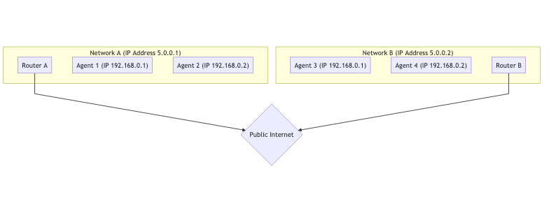
Pour les hôtes du même réseau, il est très facile de se connecter. La communication entre 192.168.0.1 -> 192.168.0.2 est facile à faire ! Ces deux hôtes peuvent se connecter l’un à l’autre sans aucune aide extérieure.
Cependant, un hôte utilisant Router B n’a aucun moyen d’accéder directement à quoi que ce soit derrière Router A. Comment feriez-vous la différence entre 192.168.0.1 derrière Router A et la même IP derrière Router B ? Ce sont des IP privées ! Un hôte utilisant Router B pourrait envoyer du trafic directement à Router A, mais la requête s’arrêterait là. Comment Router A sait-il à quel hôte il doit transférer le message ?
Restrictions de protocole #
Certains réseaux n’autorisent pas du tout le trafic UDP, ou peut-être qu’ils n’autorisent pas TCP. Certains réseaux peuvent avoir une MTU (Maximum Transmission Unit) très faible. Il y a beaucoup de variables que les administrateurs réseau peuvent changer qui peuvent rendre la communication difficile.
Règles de pare-feu/IDS #
Un autre est l’“inspection approfondie des paquets” et d’autres filtrages intelligents. Certains administrateurs réseau exécutent des logiciels qui essaient de traiter chaque paquet. Souvent, ce logiciel ne comprend pas WebRTC, donc il le bloque parce qu’il ne sait pas quoi faire, par exemple en traitant les paquets WebRTC comme des paquets UDP suspects sur un port arbitraire qui n’est pas sur liste blanche.
Mappage NAT #
Le mappage NAT (Network Address Translation) est la magie qui rend possible la connectivité de WebRTC. C’est ainsi que WebRTC permet à deux pairs dans des sous-réseaux complètement différents de communiquer, résolvant le problème “pas dans le même réseau” ci-dessus. Bien qu’il crée de nouveaux défis, expliquons d’abord comment fonctionne le mappage NAT.
Il n’utilise pas de relais, de proxy ou de serveur. Encore une fois, nous avons Agent 1 et Agent 2 et ils sont dans des réseaux différents. Cependant, le trafic circule complètement. Visualisé, cela ressemble à ceci :
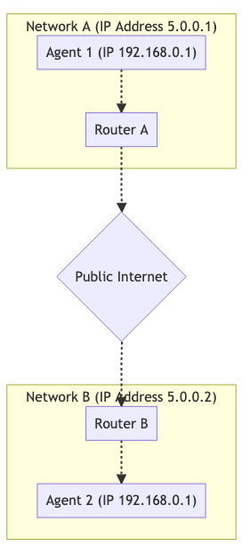
Pour faire fonctionner cette communication, vous établissez un mappage NAT. L’Agent 1 utilise le port 7000 pour établir une connexion WebRTC avec l’Agent 2. Cela crée une liaison de 192.168.0.1:7000 à 5.0.0.1:7000. Cela permet ensuite à l’Agent 2 d’atteindre l’Agent 1 en envoyant des paquets à 5.0.0.1:7000. Créer un mappage NAT comme dans cet exemple est comme une version automatisée de la redirection de port dans votre routeur.
L’inconvénient du mappage NAT est qu’il n’y a pas une seule forme de mappage (par exemple, la redirection de port statique), et le comportement est incohérent entre les réseaux. Les FAI et les fabricants de matériel peuvent le faire de différentes manières. Dans certains cas, les administrateurs réseau peuvent même le désactiver.
La bonne nouvelle est que la gamme complète des comportements est comprise et observable, de sorte qu’un agent ICE est capable de confirmer qu’il a créé un mappage NAT, et les attributs du mappage.
Le document qui décrit ces comportements est la RFC 4787.
Création d’un mappage #
Créer un mappage est la partie la plus facile. Lorsque vous envoyez un paquet à une adresse en dehors de votre réseau, un mappage est créé ! Un mappage NAT est juste une IP publique temporaire et un port qui sont alloués par votre NAT. Le message sortant sera réécrit pour avoir son adresse source donnée par la nouvelle adresse de mappage. Si un message est envoyé au mappage, il sera automatiquement routé vers l’hôte à l’intérieur du NAT qui l’a créé. Les détails autour des mappages sont là où cela devient compliqué.
Comportements de création de mappage #
La création de mappage se divise en trois catégories différentes :
Mappage indépendant du point de terminaison #
Un mappage est créé pour chaque expéditeur à l’intérieur du NAT. Si vous envoyez deux paquets à deux adresses distantes différentes, le mappage NAT sera réutilisé. Les deux hôtes distants verraient la même IP et le même port source. Si les hôtes distants répondent, ce sera renvoyé au même écouteur local.
C’est le meilleur scénario. Pour qu’un appel fonctionne, au moins un côté DOIT être de ce type.
Mappage dépendant de l’adresse #
Un nouveau mappage est créé chaque fois que vous envoyez un paquet à une nouvelle adresse. Si vous envoyez deux paquets à différents hôtes, deux mappages seront créés. Si vous envoyez deux paquets au même hôte distant mais à des ports de destination différents, un nouveau mappage ne sera PAS créé.
Mappage dépendant de l’adresse et du port #
Un nouveau mappage est créé si l’IP ou le port distant est différent. Si vous envoyez deux paquets au même hôte distant, mais à des ports de destination différents, un nouveau mappage sera créé.
Comportements de filtrage de mappage #
Le filtrage de mappage est l’ensemble des règles concernant qui est autorisé à utiliser le mappage. Ils se répartissent en trois classifications similaires :
Filtrage indépendant du point de terminaison #
N’importe qui peut utiliser le mappage. Vous pouvez partager le mappage avec plusieurs autres pairs, et ils pourraient tous y envoyer du trafic.
Filtrage dépendant de l’adresse #
Seul l’hôte pour lequel le mappage a été créé peut utiliser le mappage. Si vous envoyez un paquet à l’hôte A, vous ne pouvez obtenir une réponse que de ce même hôte. Si l’hôte B tente d’envoyer un paquet à ce mappage, il sera ignoré.
Filtrage dépendant de l’adresse et du port #
Seuls l’hôte et le port pour lesquels le mappage a été créé peuvent utiliser ce mappage. Si vous envoyez un paquet à A:5000, vous ne pouvez obtenir une réponse que de ce même hôte et port. Si A:5001 tente d’envoyer un paquet à ce mappage, il sera ignoré.
Actualisation du mappage #
Il est recommandé que si un mappage n’est pas utilisé pendant 5 minutes, il devrait être détruit. Ceci est entièrement à la discrétion du FAI ou du fabricant de matériel.
STUN #
STUN (Session Traversal Utilities for NAT) est un protocole qui a été créé juste pour travailler avec les NAT. C’est une autre technologie qui précède WebRTC (et ICE !). Il est défini par la RFC 8489, qui définit également la structure des paquets STUN. Le protocole STUN est également utilisé par ICE/TURN.
STUN est utile car il permet la création programmatique de mappages NAT. Avant STUN, nous étions capables de créer un mappage NAT, mais nous n’avions aucune idée de quelle était l’IP et le port de celui-ci ! STUN vous donne non seulement la capacité de créer un mappage, mais vous donne également les détails afin que vous puissiez les partager avec d’autres, afin qu’ils puissent vous renvoyer du trafic via le mappage que vous venez de créer.
Commençons par une description basique de STUN. Plus tard, nous développerons sur l’utilisation de TURN et ICE. Pour l’instant, nous allons juste décrire le flux requête/réponse pour créer un mappage. Ensuite, nous parlerons de comment obtenir les détails de celui-ci pour les partager avec d’autres. C’est le processus qui se produit lorsque vous avez un serveur stun: dans vos URL ICE pour une PeerConnection WebRTC. En bref, STUN aide un point de terminaison derrière un NAT à déterminer quel mappage a été créé en demandant à un serveur STUN à l’extérieur du NAT de rapporter ce qu’il observe.
Structure du protocole #
Chaque paquet STUN a la structure suivante :
 0                   1                   2                   3
 0 1 2 3 4 5 6 7 8 9 0 1 2 3 4 5 6 7 8 9 0 1 2 3 4 5 6 7 8 9 0 1
+-+-+-+-+-+-+-+-+-+-+-+-+-+-+-+-+-+-+-+-+-+-+-+-+-+-+-+-+-+-+-+-+
|0 0|     STUN Message Type     |         Message Length        |
+-+-+-+-+-+-+-+-+-+-+-+-+-+-+-+-+-+-+-+-+-+-+-+-+-+-+-+-+-+-+-+-+
|                         Magic Cookie                          |
+-+-+-+-+-+-+-+-+-+-+-+-+-+-+-+-+-+-+-+-+-+-+-+-+-+-+-+-+-+-+-+-+
|                                                               |
|                     Transaction ID (96 bits)                  |
|                                                               |
+-+-+-+-+-+-+-+-+-+-+-+-+-+-+-+-+-+-+-+-+-+-+-+-+-+-+-+-+-+-+-+-+
|                             Data                              |
+-+-+-+-+-+-+-+-+-+-+-+-+-+-+-+-+-+-+-+-+-+-+-+-+-+-+-+-+-+-+-+-+
Type de message STUN #
Chaque paquet STUN a un type. Pour l’instant, nous ne nous soucions que des suivants :
- Binding Request -
0x0001 - Binding Response -
0x0101
Pour créer un mappage NAT, nous faisons une Binding Request. Ensuite, le serveur répond avec une Binding Response.
Longueur du message #
C’est la longueur de la section Data. Cette section contient des données arbitraires qui sont définies par le Message Type.
Magic Cookie #
La valeur fixe 0x2112A442 en ordre d’octets réseau, elle aide à distinguer le trafic STUN des autres protocoles.
ID de transaction #
Un identifiant de 96 bits qui identifie de manière unique une requête/réponse. Cela vous aide à associer vos requêtes et réponses.
Données #
Les données contiendront une liste d’attributs STUN. Un attribut STUN a la structure suivante :
0                   1                   2                   3
 0 1 2 3 4 5 6 7 8 9 0 1 2 3 4 5 6 7 8 9 0 1 2 3 4 5 6 7 8 9 0 1
+-+-+-+-+-+-+-+-+-+-+-+-+-+-+-+-+-+-+-+-+-+-+-+-+-+-+-+-+-+-+-+-+
|         Type                  |            Length             |
+-+-+-+-+-+-+-+-+-+-+-+-+-+-+-+-+-+-+-+-+-+-+-+-+-+-+-+-+-+-+-+-+
|                         Value (variable)                ....
+-+-+-+-+-+-+-+-+-+-+-+-+-+-+-+-+-+-+-+-+-+-+-+-+-+-+-+-+-+-+-+-+
La STUN Binding Request n’utilise aucun attribut. Cela signifie qu’une STUN Binding Request ne contient que l’en-tête.
La STUN Binding Response utilise un XOR-MAPPED-ADDRESS (0x0020). Cet attribut contient une IP et un port. C’est l’IP et le port du mappage NAT qui est créé !
Créer un mappage NAT #
Créer un mappage NAT en utilisant STUN ne nécessite que l’envoi d’une requête ! Vous envoyez une STUN Binding Request au serveur STUN. Le serveur STUN répond alors avec une STUN Binding Response.
Cette STUN Binding Response contiendra l’Adresse mappée. L’Adresse mappée est la façon dont le serveur STUN vous voit et est votre mappage NAT.
L’Adresse mappée est ce que vous partageriez si vous vouliez que quelqu’un vous envoie des paquets.
Les gens appelleront également l’Adresse mappée votre IP publique ou Candidat réflexif de serveur.
Détermination du type de NAT #
Malheureusement, l’Adresse mappée peut ne pas être utile dans tous les cas. Si elle est Dépendante de l'adresse, seul le serveur STUN peut vous renvoyer du trafic. Si vous la partagez et qu’un autre pair essaie d’envoyer des messages, ils seront abandonnés. Cela la rend inutile pour communiquer avec d’autres. Vous pouvez trouver que le cas Dépendant de l'adresse est en fait résolvable, si l’hôte qui exécute le serveur STUN peut également transférer des paquets pour vous au pair ! Cela nous mène à la solution utilisant TURN ci-dessous.
La RFC 5780 définit une méthode pour exécuter un test afin de déterminer votre type de NAT. Ceci est utile car vous sauriez à l’avance si une connectivité directe est possible.
TURN #
TURN (Traversal Using Relays around NAT) est défini dans la RFC 8656 et est la solution lorsque la connectivité directe n’est pas possible. Cela pourrait être parce que vous avez deux types de NAT incompatibles, ou peut-être ne peuvent-ils pas parler le même protocole ! TURN peut également être utilisé à des fins de confidentialité. En faisant passer toute votre communication par TURN, vous obscurcissez l’adresse réelle du client.
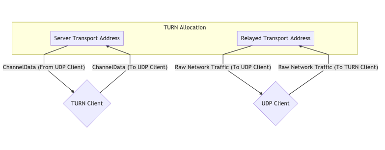
TURN utilise un serveur dédié. Ce serveur agit comme un proxy pour un client. Le client se connecte à un serveur TURN et crée une Allocation. En créant une allocation, un client obtient une IP/Port/Protocole temporaire qui peut être utilisé pour renvoyer du trafic au client. Ce nouvel écouteur est connu comme l’Adresse de transport relayée. Pensez-y comme à une adresse de transfert, vous la donnez pour que d’autres puissent vous envoyer du trafic via TURN ! Pour chaque pair auquel vous donnez l’Adresse de transport relayée, vous devez créer une nouvelle Permission pour permettre la communication avec vous.
Lorsque vous envoyez du trafic sortant via TURN, il est envoyé via l’Adresse de transport relayée. Lorsqu’un pair distant reçoit du trafic, il le voit provenir du serveur TURN.
Cycle de vie TURN #
Voici tout ce qu’un client qui souhaite créer une allocation TURN doit faire. Communiquer avec quelqu’un qui utilise TURN ne nécessite aucune modification. L’autre pair obtient une IP et un port, et il communique avec comme n’importe quel autre hôte.
Allocations #
Les allocations sont au cœur de TURN. Une allocation est essentiellement une “session TURN”. Pour créer une allocation TURN, vous communiquez avec l’Adresse de transport du serveur TURN (généralement le port 3478).
Lors de la création d’une allocation, vous devez fournir ce qui suit :
- Nom d’utilisateur/Mot de passe - La création d’allocations TURN nécessite une authentification.
- Transport d’allocation - Le protocole de transport entre le serveur (
Adresse de transport relayée) et les pairs, peut être UDP ou TCP. - Even-Port - Vous pouvez demander des ports séquentiels pour plusieurs allocations, pas pertinent pour WebRTC.
Si la requête réussit, vous obtenez une réponse avec le serveur TURN avec les attributs STUN suivants dans la section Data :
XOR-MAPPED-ADDRESS-Adresse mappéeduClient TURN. Lorsque quelqu’un envoie des données à l’Adresse de transport relayée, c’est là qu’elles sont transférées.RELAYED-ADDRESS- C’est l’adresse que vous donnez aux autres clients. Si quelqu’un envoie un paquet à cette adresse, il est relayé au client TURN.LIFETIME- Combien de temps jusqu’à ce que cette allocation TURN soit détruite. Vous pouvez prolonger la durée de vie en envoyant une requêteRefresh.
Permissions #
Un hôte distant ne peut pas envoyer dans votre Adresse de transport relayée jusqu’à ce que vous créiez une permission pour lui. Lorsque vous créez une permission, vous dites au serveur TURN que cette IP et ce port sont autorisés à envoyer du trafic entrant.
L’hôte distant doit vous donner l’IP et le port tels qu’ils apparaissent au serveur TURN. Cela signifie qu’il devrait envoyer une STUN Binding Request au serveur TURN. Un cas d’erreur courant est qu’un hôte distant enverra une STUN Binding Request à un serveur différent. Ils vous demanderont ensuite de créer une permission pour cette IP.
Disons que vous voulez créer une permission pour un hôte derrière un Mappage dépendant de l'adresse. Si vous générez l’Adresse mappée à partir d’un serveur TURN différent, tout le trafic entrant sera abandonné. Chaque fois qu’ils communiquent avec un hôte différent, cela génère un nouveau mappage. Les permissions expirent après 5 minutes si elles ne sont pas actualisées.
SendIndication/ChannelData #
Ces deux messages sont pour que le client TURN envoie des messages à un pair distant.
SendIndication est un message autonome. À l’intérieur se trouvent les données que vous souhaitez envoyer, et à qui vous souhaitez les envoyer. C’est du gaspillage si vous envoyez beaucoup de messages à un pair distant. Si vous envoyez 1 000 messages, vous répéterez leur adresse IP 1 000 fois !
ChannelData vous permet d’envoyer des données, mais pas de répéter une adresse IP. Vous créez un canal avec une IP et un port. Vous envoyez ensuite avec le ChannelId, et l’IP et le port seront remplis côté serveur. C’est le meilleur choix si vous envoyez beaucoup de messages.
Actualisation #
Les allocations se détruiront automatiquement. Le client TURN doit les actualiser avant le LIFETIME donné lors de la création de l’allocation.
Utilisation de TURN #
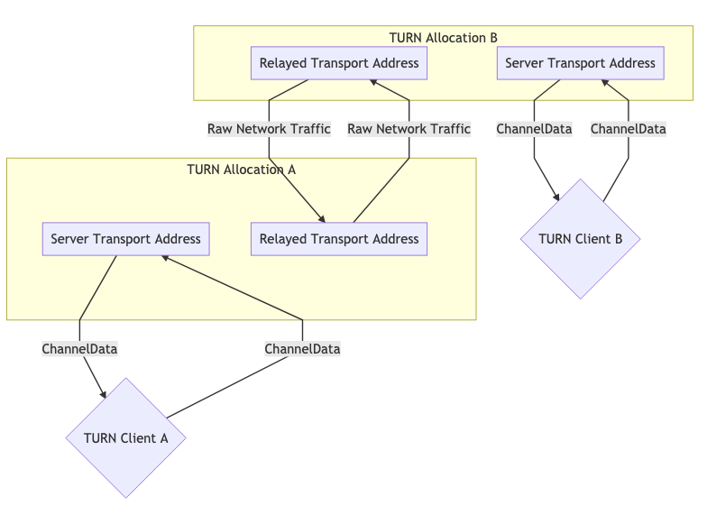
L’utilisation de TURN existe sous deux formes. Habituellement, vous avez un pair agissant comme un “client TURN” et l’autre côté communiquant directement. Dans certains cas, vous pourriez avoir l’utilisation de TURN des deux côtés, par exemple parce que les deux clients sont dans des réseaux qui bloquent UDP et donc la connexion aux serveurs TURN respectifs se fait via TCP.
Ces diagrammes aident à illustrer à quoi cela ressemblerait.
Une allocation TURN pour la communication #
Deux allocations TURN pour la communication #
ICE #
ICE (Interactive Connectivity Establishment) est la façon dont WebRTC connecte deux agents. Défini dans la RFC 8445, c’est une autre technologie qui précède WebRTC ! ICE est un protocole pour établir la connectivité. Il détermine toutes les routes possibles entre les deux pairs et s’assure ensuite que vous restez connecté.
Ces routes sont connues comme des Paires de candidats, qui est un appariement d’une adresse de transport locale et distante. C’est là que STUN et TURN entrent en jeu avec ICE. Ces adresses peuvent être votre adresse IP locale plus un port, un mappage NAT, ou une Adresse de transport relayée. Chaque côté rassemble toutes les adresses qu’ils veulent utiliser, les échange, puis tente de se connecter !
Deux agents ICE communiquent en utilisant des paquets ping ICE (ou formellement appelés vérifications de connectivité) pour établir la connectivité. Après l’établissement de la connectivité, ils peuvent envoyer toutes les données qu’ils veulent. Ce sera comme utiliser un socket normal. Ces vérifications utilisent le protocole STUN.
Création d’un agent ICE #
Un agent ICE est soit Controlling soit Controlled. L’agent Controlling est celui qui décide de la Paire de candidats sélectionnée. Habituellement, le pair envoyant l’offre est le côté contrôlant.
Chaque côté doit avoir un fragment utilisateur et un mot de passe. Ces deux valeurs doivent être échangées avant même que les vérifications de connectivité puissent commencer. Le fragment utilisateur est envoyé en texte clair et est utile pour démultiplexer plusieurs sessions ICE.
Le mot de passe est utilisé pour générer un attribut MESSAGE-INTEGRITY. À la fin de chaque paquet STUN, il y a un attribut qui est un hachage du paquet entier utilisant le mot de passe comme clé. Ceci est utilisé pour authentifier le paquet et s’assurer qu’il n’a pas été altéré.
Pour WebRTC, toutes ces valeurs sont distribuées via la Description de session comme décrit dans le chapitre précédent.
Collecte de candidats #
Nous devons maintenant rassembler toutes les adresses possibles auxquelles nous sommes joignables. Ces adresses sont connues comme des candidats.
Host #
Un candidat Host écoute directement sur une interface locale. Cela peut être UDP ou TCP.
mDNS #
Un candidat mDNS est similaire à un candidat host, mais l’adresse IP est obscurcie. Au lieu d’informer l’autre côté de votre adresse IP, vous leur donnez un UUID comme nom d’hôte. Vous configurez ensuite un écouteur multicast, et répondez si quelqu’un demande l’UUID que vous avez publié.
Si vous êtes dans le même réseau que l’agent, vous pouvez vous trouver via Multicast. Si vous n’êtes pas dans le même réseau, vous ne pourrez pas vous connecter (à moins que l’administrateur réseau n’ait explicitement configuré le réseau pour permettre aux paquets Multicast de traverser).
Ceci est utile à des fins de confidentialité. Un utilisateur pourrait découvrir votre adresse IP locale via WebRTC avec un candidat Host (sans même essayer de se connecter à vous), mais avec un candidat mDNS, maintenant ils n’obtiennent qu’un UUID aléatoire.
Server Reflexive #
Un candidat Server Reflexive est généré en faisant une STUN Binding Request à un serveur STUN.
Lorsque vous obtenez la STUN Binding Response, le XOR-MAPPED-ADDRESS est votre candidat Server Reflexive.
Peer Reflexive #
Un candidat Peer Reflexive est créé lorsque le pair distant reçoit votre requête à partir d’une adresse précédemment inconnue du pair. À la réception, le pair rapporte (réfléchit) ladite adresse vers vous. Le pair sait que la requête a été envoyée par vous et non par quelqu’un d’autre parce qu’ICE est un protocole authentifié.
Cela se produit couramment lorsqu’un candidat Host communique avec un candidat Server Reflexive qui est dans un sous-réseau différent, ce qui entraîne la création d’un nouveau mappage NAT. Rappelez-vous que nous avons dit que les vérifications de connectivité sont en fait des paquets STUN ? Le format de la réponse STUN permet naturellement à un pair de rapporter l’adresse peer-reflexive.
Relay #
Un candidat Relay est généré en utilisant un serveur TURN.
Après la négociation initiale avec le serveur TURN, vous recevez une RELAYED-ADDRESS, c’est votre candidat Relay.
Vérifications de connectivité #
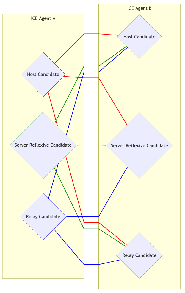
Nous connaissons maintenant le fragment utilisateur, le mot de passe et les candidats de l’agent distant. Nous pouvons maintenant essayer de nous connecter ! Chaque candidat est apparié avec chaque autre. Donc, si vous avez 3 candidats de chaque côté, vous avez maintenant 9 paires de candidats.
Visuellement, cela ressemble à ceci :
Sélection de candidat #
Les agents Controlling et Controlled commencent tous deux à envoyer du trafic sur chaque paire. Ceci est nécessaire si un agent est derrière un Mappage dépendant de l'adresse, cela causera la création d’un Candidat Peer Reflexive.
Chaque Paire de candidats qui a vu du trafic réseau est ensuite promue en une paire Valid Candidate. L’agent Controlling prend ensuite une paire Valid Candidate et la nomme. Cela devient la Paire nominée. Les agents Controlling et Controlled tentent ensuite un autre tour de communication bidirectionnelle. Si cela réussit, la Paire nominée devient la Paire de candidats sélectionnée ! Cette paire est ensuite utilisée pour le reste de la session.
Redémarrages #
Si la Paire de candidats sélectionnée cesse de fonctionner pour une raison quelconque (le mappage NAT expire, le serveur TURN plante), l’agent ICE passera à l’état Failed. Les deux agents peuvent être redémarrés et feront tout le processus à nouveau.